
We sometimes receive requests for help, for example to understand why the engine turns off on a straight without an apparent reason .
Often a wrong installation of the ECU, causing too much vibration, will impact the IMU ( Inertial Measurement Unit ) installed on board the ECU .
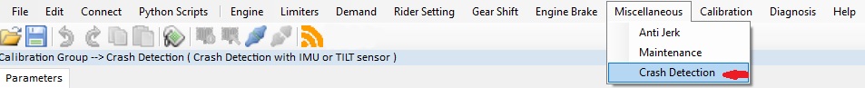
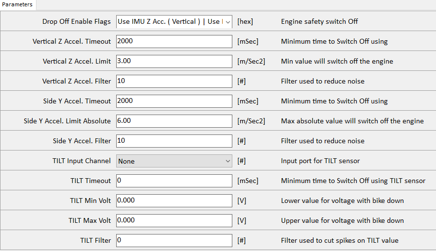
The Next Generation firmware families , offer the possibility to configure the Crash Detection strategy , You can find it found here :
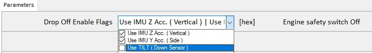
The crash detection strategy can be linked to the internal IMU or to an external tilt sensor.
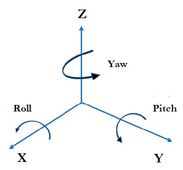
When using the internal IMU, the Channels CRASH_ACC_Z and CRASH_ACC_Y (in some firmware versions BIKE_ACC_Z and BIKE_ACC_Y)are used for the strategy calibration. The axes reference that are used for strategy , are shown below and are relative to the motorcycle, NOT to the ground ,NOT to the ECU .
X direction is front of motorbike , Z direction is UP .
CRASH_ACC_Z has usually values around 9 (9,8 m/s2) and CRASH_ACC_Y around 0 (0 m/s2) when the motorcycle is upright, with zero roll.
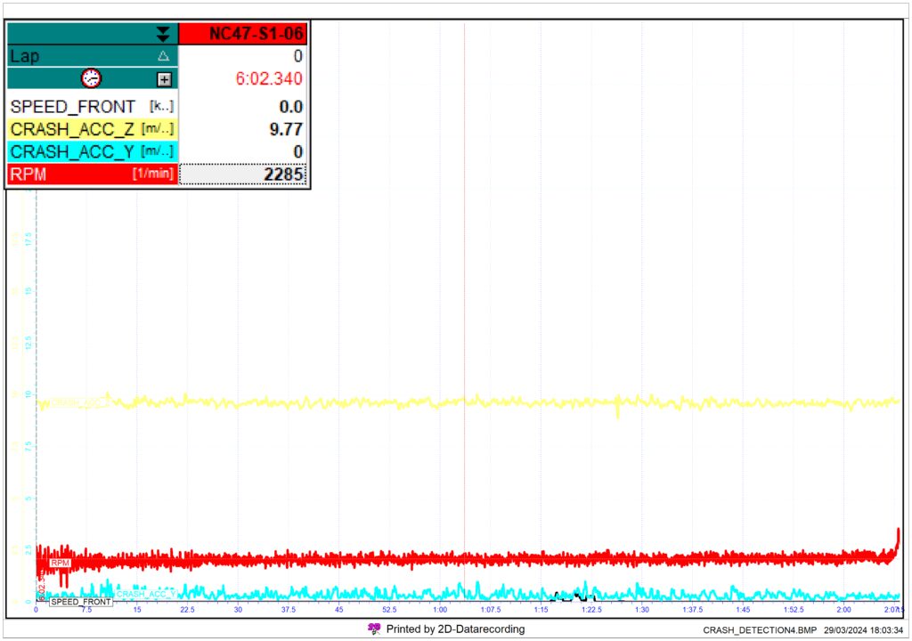
In the calibration page the main parameters are the Vertical Z Accel. Lower limit and it’s timeout, and Side Y Accel. Limit Absolute and it’s timeout. These parameters are linked to CRASH_ACC_Z and CRASH_ACC_Y.
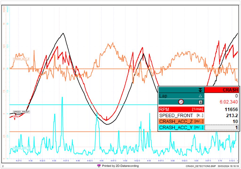
The values of the channels CRASH_ACC_Z and CRASH_ACC_Y may fluctuate alot while riding as shown by the graph below. The flat lines are rulers that have been added, for this example, at 3 m/s2 , at 6 m/s2 , that are the limits shown in the strategy calibration page above and 10 m/s2the average value. CRASH_ACC_Y crosses the limit once but not for long enough (time) to trigger the strategy (timeout parameter is set as 2000 msec). To trigger the strategy the value must CONTINOUSLY be over (Y) or under (Z) the set limit.
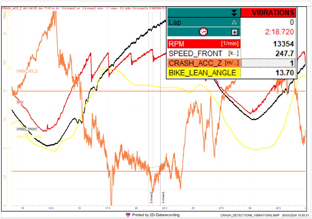
When the motorcycle is lying down (or even upsidedown) the value of the channel CRASH_ACC_Z should be lower than 3. The value of CRASH_ACC_Y, only when the bike is lying on the side, should be above 6. In the graph below vertical vibrations of the engine hamper the ability of the accelerometer to measure correctly the vertical acceleration. This happens when the ECU is directly and solidly connected to the frame. When vibrations are giving issues to the IMU it can be easily seen on straights, where vertical vibrations make the accelerometer measure strange low values. The two flat lines show: the average value the channel should have on a flat straight (9-10) and the lower limit of the crash startegy (3). The averege in this example is about 3.3and stays below 3 for more than one second.
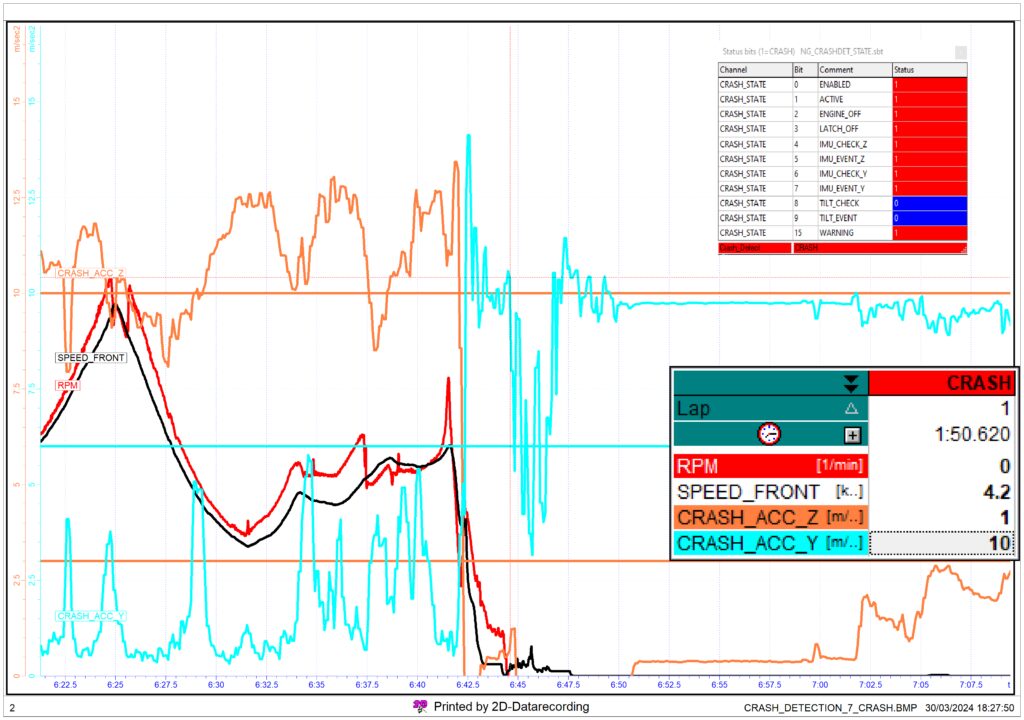
In the graph shown under, a crash after a high-side. The system is well calibrated, the crash startegy activates 2 seconds (timeout) after the impact, the engine is turned off before the bike stops sliding (front wheel speed shows small spikes of acceleration with engine off given by impacts with the ground while sliding). In the graph below a useful bitmask is shown for the crash strategy.
You should always use the CRASH_STATE channel on data acquisition , to evaluate what are happening to the strategy .
To avoid issues :
- Remember that the strategy works with accelerometers and not with lean angle.
- Remember to perform the IMU ZERO procedure when installing the ECU on the bike. Check readings (acc and angle) once in a while.
- Vertical vibrations may mess up the Z accelerometer readings, but Y is usually unaffected. Y can be used alone, if Z values are unreliable, as a workaround.
- CRASH_ACC_Z and CRASH_ACC_Y are filtered channels made for the startegy. CRASH_ACC_Y is an absolute value (will not go negative on one side or the other).
- Where and how the ECU is placed on the bike is fundamental. Metal to metal contact between the frame and the ECU has to be avoided. Any hard contact may transfer vibrations.
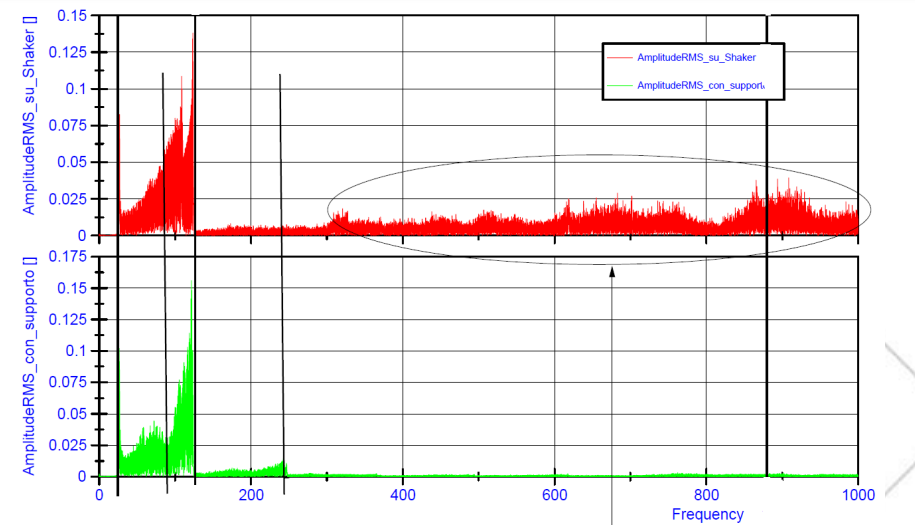
Vibrations may be filtered out if the ECU is protected by the correct material, not too soft nor too hard. Under a link to the cover for the ECU used to filter out vibrations above 100 Hz.
To use this cover at it’s best, the ECU should be placed flat ( Z axis of ECU must be UP ) , using the holder kit as point of contact with the vehicle.