The main rule to solve a problem , ofter valid in other field , is to follow a line from INPUT to CONTROLLER and finally the OUTPUT .
In our case the INPUT is the sensor , the CONTROLLER is the strategy and the OUTPUT can be checked on data acquistion .
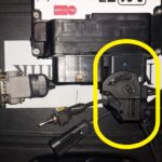
Sensor Setup ( the INPUT )
To setup correctly the Gear Shift some simple checks should be made .
First of all the Load Cell Sensor should be checked :
- Configure the Load Cell sensor ( menu calibration /load cell force )
- Set the Offset to the same value You read on Load Cell Analog channel
- Set the Gain to the value You can read on Your sensor datasheet ( usually 500 N/Volt ) , set the sign ( + or – ) to obtain a positive value on Load Cell Force channel applying a force to increase gear ( 1->2->3 and so on … )
Strategy Setup ( the CONTROLLER )
For Gear Shift Up :
- Enable the gearshift from Working Modes ( menu Rider Setting / Workmode Setting )
- Setup the basic features only ( menu Gear Shift / Gear Shift Up Enable )
- All Options = OFF
- Debounce Time = 200 mSec
- ReArm Force = 150 N
- Trigger Force = 250 N
- Min GAS = 20 %
- Min SPEED = 0 km/h
- Setup the CUTS ( menu Gear Shift / Gear Shift Up Cuts )
- TDC Loop Size = 10
- For All gear ( included default ) Set Cut Timeout = 70
- Switch OFF both IGNITION and INJECTION ( menu Gear Shift / Gear Shift Up Cuts )
- Set INJECTION Pattern #1 = 00000000
- Set IGNITION Pattern #1 = 00000000
For Gear Shift Down :
- Enable the gearshift from Working Modes ( menu Rider Setting / Workmode Setting )
- Setup the basic features only ( menu Gear Shift / Gear Shift Down Enable )
- All Options = OFF
- Debounce Time = 200 mSec
- ReArm Force = -150 N
- Trigger Force = -250 N
- Max GAS = 10%
- Min SPEED = 0 km/h
- Setup the BLIP ( menu Gear Shift / Gear Shift Down Blip )
- For All gear ( included default ) Set Cut Timeout = 200
- Setup the whole table for Target TPS = 20 %
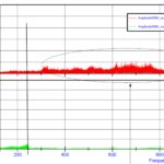
Data acquistion check ( the OUTPUT )
After setting up everithing here above , You can check what happens on data acquistion . You could setup Your data analyzer with following channels :
- RPM , TPS , SPEED
- LOADCELL , GEAR_POS
- CUT_LEVEL , CUT_FUNCTION , STR_FUNCTION
- GEARSHIFT_UP_SM , GEARSHIFT_DN_SM
It would be perfect if You can show STR_FUNCTION using a BIT MASK instruments ( You could check Your data analyzer functionality ) . Check the Supersport Channels Explained post for more details .
Now You can check if all “chain” work like should .
So when rider press pedal ( LOADCELL ) value pass the TRIGGER THRESHOLD , then the STR_FUNCTION must signal the GEAR SHIFT strategy active , and CUT_LEVEL must be 100 % ( for GearShift Up ) , and TPS move up ( for GearShift Down ) .
If something don’t happens like expected , made some step back and check Your configuration .
For a detailed description We advise to read carefully following documents :