Often problems come from wiring looms , and this are caused by following reasons :
- Failure due to crash
- Failure due to bad manufacturing
- Failure due to bad design
So …. first of all the schematic drawings sould be made following some simple rules :
- Twist cables for actuators with high current ( expecially in case the actuator have inductive impedence , and the command is with a PWM or pulsed ) . This is true expecially for : electric motors ( Ride By Wire ) , coils , and injectors , lambda heater .
- Use twisted and shielded cables , sensors for pulses : Pickups for Crank and Cam , Speed
- Use twisted and shielded cables very low current sensors : Lambda
- Use twisted and shielded cables CAN BUS lines
- Use twisted and shielded cables for safety relevant sensors : GAS and TPS if used for Ride By Wire
- Keep High current cables ( e.g. coils ) far as spossible from sensitive sensors ( e.g. Pickup ) . This is a consideration about layout .
- Use fuses to protect Control Units ( e.g. from reverse polarity )
- Use separate fuses for critical sensors / actuators ( speed sensors , lambda , quick shift sensor ) , so to prevent ECU switch off in case of problem to this auxigliary devices .
- Connect the shield to power ground , on one side only , this will prevent current loop on the shield conductor
- Connect all the power ground on the same point on engine
- Use only 1 cable to connect engine anc battery ground
- Follow the requirements about Power Supply , described on Control Units documentation
- Follow the requirements for Molex connectors ( for MKE7 and MKE5 ECUs )
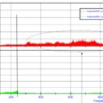
Twisting high current cables , will limit the electromagnetic noises emission .
For similar reasons , twisting and shielding cables for sensors , will limit the electromagnetic noises capture .
If You are designing a wiring loom for MKE5 and MKE7 , We strongly advise to read carefully the documents here below :


